Moderated newsgroup PARTS RECYCLING for somebody LOOKING OR SELLING.... > Auto Parts
> Automobiles
> Axiom CME564 development board system
Axiom CME564 development board system
What is for sale: Axiom CME564 development board system
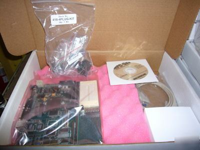
AXIOM CME564 DEVELOPMENT BOARD SYSTEM NIB
The CME-564 (MPC564EVB) is a development system for the Motorola MPC564 PowerPC microcontroller. The system provides for development of target applications for the similar MPC561, MPC562, or MPC563 microcontrollers also. The system is Plug and Play with the supplied Debug Monitor firmware in the on-board flash memory. Other features include 512K Byte (128K x 32) Synchronous SRAM development or application memory, 2M Byte (512K x 32) Synchronous FLASH, RS232, CAN and Ethernet Communication Interfaces, Keypad and LCD Module support, and the Power Oak regulated supply source. The kit provides Serial Cable, Ethernet Cable, Universal Wall Plug power source, printed hardware manual, and the MPC5xx support CD with programming utilities, example software, support software, and technical manuals. Note: Due to limitations of peripherals attached to the MPC564 bus ports this board should not be applied for single-chip mode application support, see the CMD-564 version for this type application.
* 512K Byte (128K x 32) Sync. SRAM, optional additional 512K Byte
* 2M Byte (512K x 32) Sync. FLASH
* 512K Byte FLASH internal to MPC564 device
* 32K Byte SRAM internal to MPC564 device
* POWER OAK (PC33394 P2.6) regulated power supply for 5V, 3.3V and 2.6V supplies.
* MAP Switch – provides easy assignment of chip selects and memory mapping.
* CONFIG Switch – Basic necessary Reset Word Configuration options.
* COM1 - SCIA1 w/ RS232 type DB9-S Connection
* COM2 - SCIA2 w/ RS232 type DB9-S Connection, TX / RX polarity option.
* CAN Ports – 3 CAN transceiver interfaced ports, 1 x 4 headers.
* 10/100T Ethernet Port – LAN91C111 based MAC+PHY, memory mapped.
* DEVELOPMENT Ports – Nexus 50 pin and dual voltage BDM Ports.
* LCD Port - LCD Module Interface Connector w/ Contrast Adjust, Buffered and Memory Mapped
* KEYPAD Port - 16 Key passive interface, applies QADC_B channels for operation.
* BUS Port – 32 data and 24 address lines on 60 pin header.
* CONTROL Port - Bus Controls with 40 pin header.
* QSM Port – Serial I/O ports with 16 pin socket headers.
* MIOS Port - MDA, PWM, and MGPIO ports with 34 pin socket header.
* TPU Ports - 2 Timing Processor I/O ports with 20 pin socket headers.
* QADC Ports - 2 Analog I/O ports, one 20 pin and one 24 pin socket header.
* IRQ Port – Interrupt or MPC564 port I/O with 10 pin socket header.
* POWER Port – Primary and standby power supply access port, no header.
* I/O Connectors in .1 grid, pin headers for bus and control provide easy ribbon cable connection for external connections. Socket headers provide easy wire connection to breadboard prototype area with 22ga solid wire.
* Large Prototyping Area with +5V and ground connection grids.
* Mictor Logic Probe connectors for the Address and Data bus (Not installed default)
* Breadboard Prototyping area (2.5 x 1.5 inch) for easy installation of test connections.
* System Indicators – Reset Indicator, Supply voltage indications for 5V, 3.3V, and 2.6V supplies
* Reset Switches – POR, Hard, Soft Reset buttons.
* User Components – 4 user indicators, 4 user Switches, 1 user Pot with socket header for I/O connection.
* Clock 56 MHz Maximum, 4Mhz reference
* Operating temperature 0°C to +70°C
* Power requirement 6 – 26V DC, 12VDC @ 300 ma Typical
* Power output 5.8V @ 1.5A output with 5V, 3.3V, and 2.6V regulated supplies
* Board Size 7.00 x 7.60 inches, 8 layers
Contact: glenda.mills@parts-recycling.com (Glenda Mills) (email hidden).